Basic Principles
Getting started
Within this guide, I currently will not cover the unboxing and assembly of the laser itself. Sculpfun (and competitors) has good tutorials, and there are multitudes on YouTube as well (the Sculpfun tutorial is here). Once you have set everything up, you are ready to go. At least nearly. The laser itself has a control board included, but without external software, it’s more or less useless. Within the next sections, I will give a short overview of the control structure.
Notes on mechanical setup
The mechanical setup is easy in general, but it also has some hurdles to jump over. First, you need to make sure that the frame is rectangular. Start by leaving all screws slightly loose, straighten the frame and then tighten the screws finally. The belts that are used by the motors to drive the gantry must be so tight that the laser head does not move / wobble freely. But they also must not be as tight that the gantry does not move anymore. A good method to check for this is the tilt test. Tilt your frame by 45°. If the gantry moves slowly downwards, then the belts are tightened correctly (no exact science, but quite ok as a test). Do this for both axes. A more elaborate guide is here.
Control board, firmware and control software
In this section, I want to give a short overview of how the control of a laser engraver works. In my experience, many questions arise from the fact that the function is not completely clear.
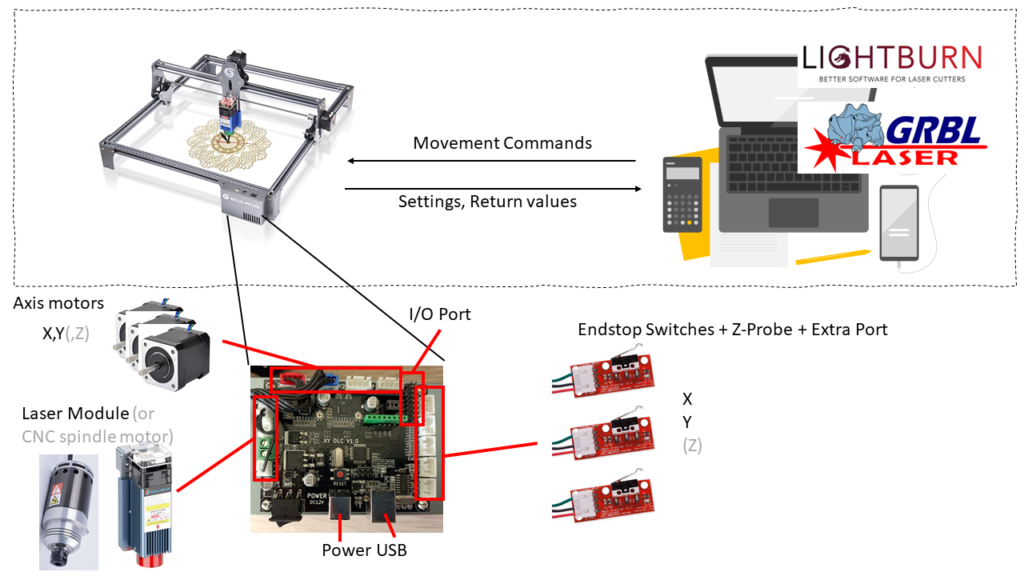
Basic structure
The laser contains a control board on which a certain firmware (piece of software to run on a microcontroller) is installed. The task of the firmware is to translate control commands from the control software on an external PC into movements and on/off switching of the laser. The control PC passes the commands to the controller in so-called “G-codes”. G-codes are/is a kind of programming language for CNC machines. Using this, motion commands and other actions can be executed. A classic G-code consists of letters and numbers. For example, “G0 X100 Y100”. This command creates a rapid linear movement to the position X=100 mm and Y=100 mm. (references: linuxcnc.org, grbl) The laser engraver control board runs a dialect called grbl (pronounced gerbil, https://github.com/gnea/grbl). This dialect is specifically designed to control CNC and laser machines. It is an open-source project and thus free to use and modify.
Excursion Firmware Functionality
In order for the firmware to execute the control commands correctly, it needs some prior knowledge about the mechanics of the machine. The firmware generates exact control commands for the motors, but motors don’t understand absolute positions, only how many steps further they should turn. This is a peculiarity of the installed so-called stepper motors.
Info stepper motors
Stepper motors are controlled step by step. Depending on the model, the step size is, e.g., 1.6 degrees. This means that 225 steps are performed for one complete revolution (360 degrees). The motor driver modules break down these steps into microsteps (e.g., 16), so that in this case 3,600 steps (360/1.6×16) result for a full revolution. Now you have to know how far the system moves during one full revolution. This must be derived from the mechanics, e.g., what kind of gear or belt drives the system. When you have calculated the steps per mm of travel with this information, the firmware can execute the movement correctly. The Sculpfun S6 / S9 mechanical setup uses 80 steps/mm. That means, the firmware need to send 80 steps to the motor for the laser head to move 1 mm.
If the physical movement does not match the intended movement, the steps/mm parameters must be adjusted accordingly. You can do this either manually, or use an assistance function like it is included in LightBurn (LightBurn Documentation)
Other interesting parameters of the firmware in this course are the maximum speeds and accelerations. Hereby, one specifies to the firmware how fast the maximum movement may be and how fast the maximum acceleration may be. These values should also be adjusted to the machine. The heavier the carriage to be moved or the weaker the motors are, the slower the machine can be operated. One can give the machine a speed of 10,000 mm/min. But if the motors cannot physically reach this speed, you get a non-deterministic behavior. The same is true for acceleration. If this is set too high, the motors either cannot achieve this acceleration or overshoot and produce a vibrating motion. If you want to get the maximum out of it, you should set the acceleration so that just no vibrations can be seen. For the speed, it is also necessary to measure which speed the mechanics can still reach. [If I have time someday, I will try to do some measurements on my Sculpfun S6 to determine optimized parameters]
In the firmware you can set some more parameters, these will be explained if they are needed in the respective situations.
The firmware parameters within the firmware all have a number and are addressed with the dollar sign $ in front. Therefore, you often see designations like “$32=1″. This means that the parameter 32 should be set to the value 1. The explanation of the parameters can be found in the description of the firmware. Tools like LightBurn or LaserGRBL also offer a graphical setting option for these parameters. You can set the parameters manually via the console. The console is a direct communication interface that displays the messages of the firmware and can also accept commands. There you can type the command as given above, “$32=1”, and this will program and save the value.
You can find additional information about the firmware in the article about firmware upgrades.
Control software
There are quite some tools available for controlling the laser. Especially popular are LightBurn and LaserGRBL. LaserWeb is another tool. I might write another article about the advantages and disadvantages of these tools. For now, this is just about the principle. When the motif is prepared in the control software, it can be sent to the microcontroller. After this process is started, the PC sends a continuous stream of commands to the microcontroller. Therefore, the connection must not be disconnected. If there are transmission errors on the way, the commands will not be understood / executed by the microcontroller. Therefore, it is important to use the shortest possible / high quality USB cable. This is a common cause of errors. Additionally, the control PC must not go into standby while lasering!
In the control software, various parameters such as speeds can be specified. These are executed by the firmware, but only within the limits set! If 3,000 mm/min is set as the maximum speed in the firmware, the movements will NOT be executed faster, even if the software specifies 6,000 mm/min! If the value sent is above the set maximum, the firmware takes its own maximum value. So it is better to stay within your firmware limits when using your laser. This leads to the best prediction results. If you send motion using 6,000 mm/min to your laser, but the firmware is set to 3,000 mm/min, LightBurn will tell you, the process takes (e.g.) 3 minutes, but in reality, it takes 6 (because it’s run on half speed).
Article reprint:https://wiki.the-iskens.com/documentation/basic-principles-of-laser-cutters-engravers/


